Laboratories and Test Facilities
Rock Mechanics Laboratory
The EMI rock mechanics laboratory includes 5 MTS test frames, of which capacities range from 20,000 to 1,000,000 lbs. The MTS machines are used for measuring many of the physical properties of rock. They are driven by, and digitally record the data via, a computer controlled closed servo loop. Typical physical property tests include: Unconfined Compressive Strength (UCS), Brazilian Tensile Strength (BTS), Triaxial Compressive Strength, and Punch Penetration Response. Much additional equipment, for determining parameters such as abrasivity, elastic constants, petrographic analysis and total hardness, exist at EMI facilities.
PHYSICAL PROPERTY MEASUREMENTS
All physical property testing is performed under strict quality control guidelines of ASTM and/or ISRM established test procedures
Unconfined Compressive Strength (UCS)
Indirect (Brazilian) Tensile Strength
In bedded/foliated rocks, particular attention needs to be given to loading direction with respect to bedding/foliation. The rock should be loaded so that breakage occurs in approximately the same direction as fracture propagation between adjacent cuts on the tunnel face. This is very important assessment in mechanical excavation by tunnel boring machines.
Cerchar Abrasivity Index
Punch Penetration Test
Acoustic Velocities and Dynamic Elastic Constants
Point Load Test
Thin Section Petrographic Analysis
Schmidt Hammer
Abrasive Mineral Content and Moh's Hardness
Static Elastic Constants
Triaxial Strength Testing
Additional Tests
Linear Cutting Tests
Linear cutting tests provide a direct measure of rock cuttability under simulated field conditions. The LCM measures the forces acting on an individual cutter while cutting actual rock. Data from this test provides input for performance prediction, machine specification, cutterhead balancing and optimization for cutting geometry. These full-scale tests eliminate the uncertainties of the rock, which may not be identified by physical property testing.
The normal force recorded by the LCM is used to calculate necessary effective mass and thrust required of the machine. This is important to ensure that the machine is able to provide the necessary thrust, so the cutters can effectively penetrate the rock. The rolling/drag force is directly related to the torque requirement of an excavator, and is used to calculate the specific energy requirement. Specific energy is defined as the amount of energy required to excavate a unit volume of rock. Using the specific energy (hp-hr/yd3), achievable production rates are calculated for a machine with a known horsepower available on the cutterhead. Lower specific energy means that a given machine will produce more material, or that a smaller/less expensive machine may be used to produce the required amount of material. The side force may be used along with normal force and rolling force to balance the cutterhead design.

The LCM features a large stiff reaction frame on which the cutter is mounted. A triaxial load cell, between the cutter and the frame, monitors forces and a linear variable displacement transducer (LVDT) monitors travel of the rock sample. The rock sample is cast in concrete within a heavy steel box to provide the necessary confinement during testing. A servo controlled hydraulic actuator forces the sample through the cutter at a preset depth of penetration, width of spacing and constant velocity. During the cut, the triaxial load cell measures the normal, rolling, and side forces acting on the cutter. After each cut the rock box is moved sideways by a preset spacing to duplicate the action of the multiple cutters on a mechanical excavator.
In field excavation, the individual cutters on the machine always operate on a rock surface damaged from the previous cutting action. This condition is duplicated in the laboratory by thoroughly conditioning the rock surface before testing began. This is accomplished by making several passes of cuts before data is collected.
LCM test equipment can be used to test different type of cutters and bits as shown in the following photos.

DRILL TEST FIXTURE (DTF)
DESCRIPTION
The Drill Test Fixture (DTF) is used for performance evaluation of drill bits and cutterheads up to 3-ft (0.9-m) in diameter. The DTF has the ability to bore axially with the drill string, as well as slew, or cutting perpendicular to the drill string. The DTF is instrumented to measure all operational parameters, as well as vibrations generated by the cutting action. These measurements are digitally recorded with a computer based data acquisition system. The testing of a full-scale cutterhead provides an accurate measure of qualifying the dynamic effects of cutting and an economic proving ground for new bits and cutterheads.
EMI’s laboratory drill rig can perform drilling and boring tests up to 3-ft (0.91 m) in diameter. Its capacity is 100,000 lbs (445 kN) of thrust and 150 hp (112 kW). Cutterhead rotational speed is variable up to 60 rpm.

The machine performs both mechanical and water jet-assisted drilling tests. The cutting action of a roadheader or drum shearer can be simulated by moving the rock sample sideways with a hydraulic actuator. A computer-based data acquisition system monitors and records all drilling parameters during testing.


The DTF can also be used to test tri-cone bits, coring bits, and new-designed bits such as drill bits equipped with mini-disc cutters. The off-center drive system also allows for installation of a swivel unit. In addition to basic drilling parameters, cutter forces and pipe stresses can also be measured and recorded during testing.
Videos:
LABORATORY TUNNEL BORING MACHINE (LTBM)
Another unique test fixture at EMI is the Laboratory Tunnel Boring Machine (LTBM). It is used to test the performance of full-scale cutterheads up to 6 feet (2 m) in diameter. It is mounted on a swivel frame so that any orientation can be tested, from straight up to straight down, in wet or dry conditions. The LTBM data acquisition system is computer based for high resolution and accuracy. Individual cutters can be instrumented to measure actual cutter forces during boring.

DESCRIPTION
A six-foot diameter, computer-controlled rotary cutting machine with removable cutters and cutterhead performs tunnel, raise and shaft boring investigations. The machine is pivoted on an anchor frame so that it can be tilted to any desired direction. The machine is used in laboratory studies to develop design guidelines to optimize tunnel, raise and shaft boring performance. All machine operative functions are servo-controlled and run by a computer system. The capacity is one million pounds of thrust and 200,000 foot-pounds torque with cutterhead speed variable up to 55 rpm. Instrumentation includes monitoring of individual cutter forces in three directions, as well as measuring all machine parameters during cutting. The machine can also be fitted with water jets to perform water jet-assisted mechanical cutting tests. The machine can also be used to run dust suppression and muck removal tests.
TESTING OF A 6-FT CUTTERHEAD


Videos:
ROTARY CUTTING MACHINE (RTC)
A 5-foot diameter, single-cutter rotary machine tests full-scale cutter bits (disc, pick, etc.) for performance and wear evaluations over long periods of time. Water jets may also be incorporated into the system to perform jet-assisted mechanical cutting tests.
ROTARY - PERCUSSION ROCK DRILLING FACILITY
The rotary drill facility permits laboratory testing and evaluation of various roof drills and bits, using an Epiroc COP1240 rotary hammer drill. The equipment includes a commercial-scale roof drill mounted on a multi-position drill boom assembly, and a heavy structural frame for holding the rock sample. The unit can also be fitted with water jets to perform water jet drilling tests.


WATER JET TESTING
Water jet equipment is available for high-speed drilling and slotting in rocks. A drill unit is mounted on a mobile self-contained chassis with a multi-position boom to enable precise positioning and angling of drill holes. A modified machining mill is used for water-jet slotting of straight and curved curfs These water-jet test stands are set up to provide a wide range of pressures and flow rates.

EMI has extensive laboratory test and
computing facilities for conducting
various rock and soil tests and fullscale
cutting and drilling tests. Data
collected during the testing processes
is then analyzed by computer models.
The laboratory facilities are continually
expanded to accommodate new
research programs requiring the design
and construction of specialized equipment.
Contact Us
New Testing and Developments
SINTEF
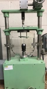
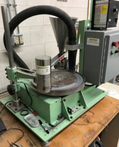
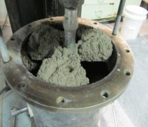
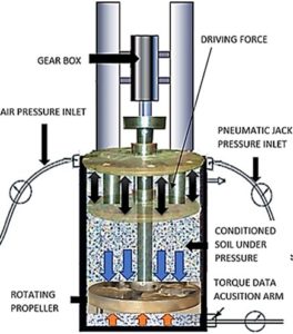
Soil Abrasion
Objective: To develop a device for direct measurement of abrasion of soil and rock fragments to predict wear on various excavation / drilling equipment.
Accomplished: A new device for testing is designed and fabricated, various types of soil and rock fragments were tested in dry, wet, and saturated conditions, elevated pressures examined, impacts of mixing of various foams and mud were tested, various types/hardness of steel/carbides tested. New Index introduced.
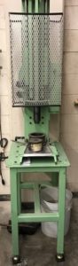
Miniature Linear Cutting Machine
A new system is being developed that will allow for small cuts and scratching of samples as small as 6 inches. The new system operates much in the same manner as the full-size Linear Cutting Machine.
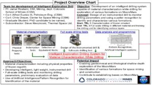
Space Resources and Mining